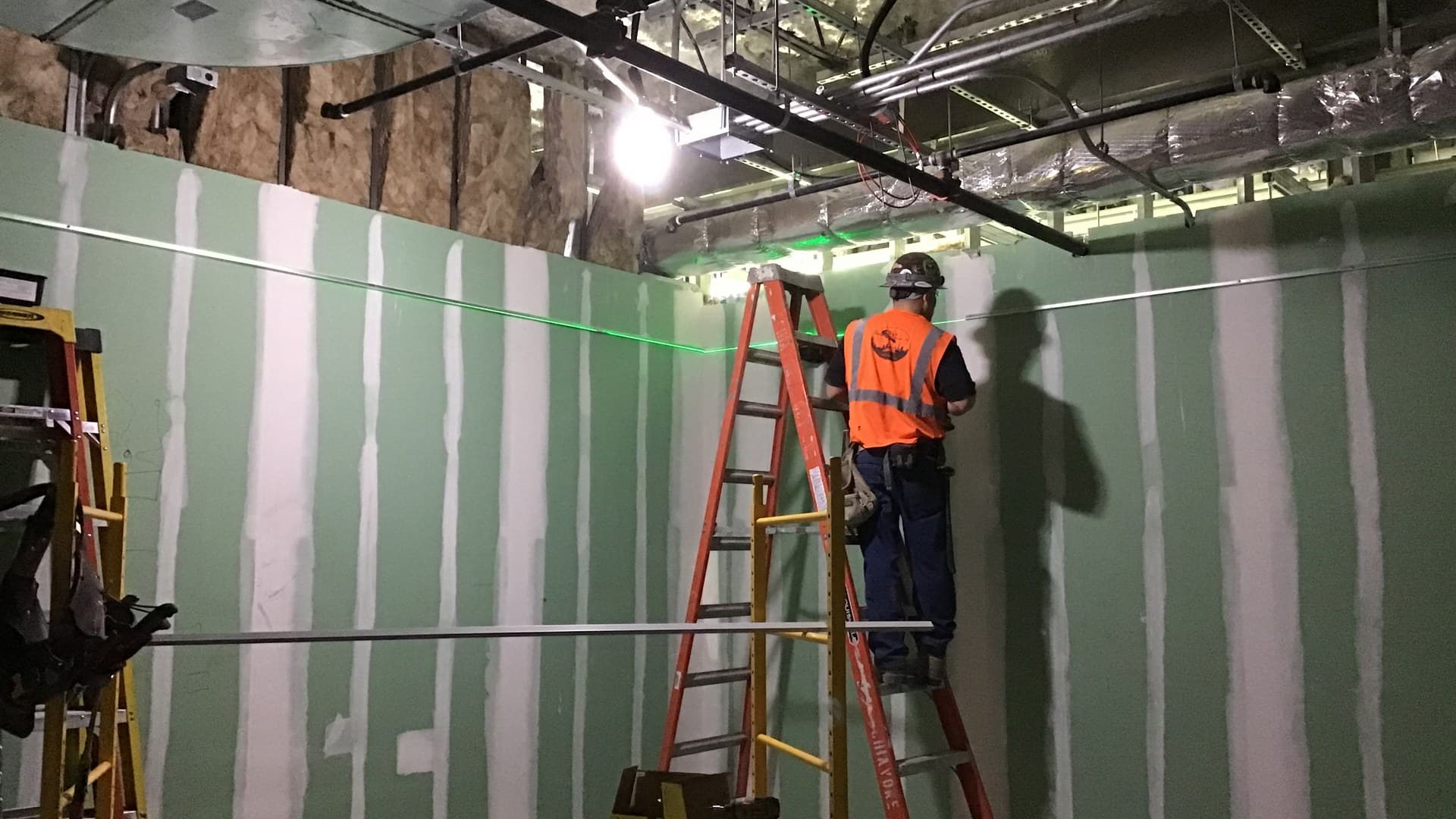
Crack-Free Drywall Partitions and Ceilings: The Complete Knauf Engineering Guide
Senior engineer's guide to building crack-proof drywall partitions and suspended ceilings: 0.6 mm steel framing, sliding perimeter joints, Kurt paper tape, and fastener depth.
Cracks in drywall systems are neither an inevitable byproduct of building settlement nor a cosmetic flaw attributable to poor paint. In 98% of cases, cracking is a structural failure of the gypsum core or joint matrix caused by shear, flexural, or hygrothermal stresses transferred directly into the drywall assembly due to framing defects and substandard joint mechanics.
This guide codifies the technical requirements of Knauf Engineering Bulletins (P 112, P 113, W 111, W 112, C 623 systems), DIN 18181 / DIN 4103, and ASTM C754 / EN 520 to build bulletproof, defect-free drywall assemblies.
1. The Structural Physics of Cracking (Why Assemblies Fail)
Gypsum plasterboard (EN 520 / ASTM C1396) features high compressive strength but exceptionally low tensile and shear resistance without its paper liner. Any unbuffered differential deflection from the building structure creates localized stress spikes that rupture the gypsum core.
1.1. Slab Deflection and Rigid Perimeter Lock
Reinforced concrete slabs and timber joists continually deflect under dead loads (structural weight, screed) and live loads (occupancy, dynamic loads, mechanical equipment).
- Standard design codes permit mid-span deflection ratios between L/250 and L/500. Across a 6-meter (20 ft) span, permissible structural sag reaches 12 to 24 mm (0.5 to 1.0 in).
- Failure Mode: If a suspended ceiling grid or partition head track is rigidly fastened to perimeter structural walls without a sliding decoupling joint, slab deflection induces catastrophic vertical shear stresses along the drywall perimeter and first framing run. The joints crack instantly under shear lock.
1.2. Hygrothermal Movement (Hygric Expansion)
Gypsum is a hygroscopic, porous crystalline material. As relative humidity (RH) fluctuates between 30% (winter heating season) and 80% (humid summer conditions), the coefficient of hygric expansion equals 0.05–0.08 mm/m (0.006–0.010 in/10 ft) per 10% RH change.
- Over a continuous 12-meter (40 ft) ceiling expanse, seasonal linear dimensional shifts can exceed 4 to 6 mm (0.15 to 0.25 in).
- Without engineered expansion control joints, cumulative compressive stress causes buckling, followed by tensile fracture along the weakest seams during the next drying cycle.
1.3. Dynamic Vibration and Kinetic Impact
Slamming a 40 kg (90 lb) solid-core door transfers instant kinetic shock into the adjacent vertical studs.
- If the drywall joint is installed flush with the door jamb corner, the concentration of principal tensile stress shears the joint compound at a 45-degree angle.
2. Substructure & Framing Mechanics
2.1. Steel Gauge Requirements: The 0.6 mm Rule
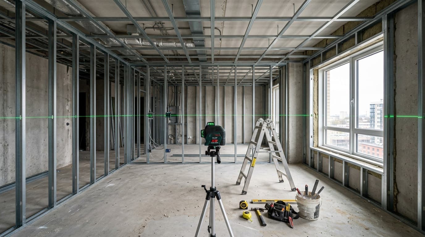
Structural rigidity in Knauf systems depends on cold-formed galvanized steel components with a nominal thickness of strictly 0.60 mm (24 gauge, DIN 18182-1 / ASTM C645).
- Failure Modes of Thin-Gauge 0.40 mm Steel:
- Fastener Stripping: Self-piercing drywall screws (TN 25) strip out when driven into 0.4 mm steel. The screw spins freely, providing zero pull-out clamp force while appearing set.
- Buckling under Load: Thin studs buckle under tile dead-load or lateral deflection, causing wide delamination cracks along board edges.
Substructure Load Capacity Comparison (3.0 m / 10 ft stud height):
| Steel Thickness | Moment of Inertia $I_x$ | Max Clear Height | Screw Strip Risk |
|---|---|---|---|
| 0.60 mm (Knauf Standard) | 4.96 cm⁴ | Up to 4.50 m (15 ft) | < 0.2% |
| 0.40 mm (Sub-spec Metal) | 2.65 cm⁴ | Up to 2.60 m (8.5 ft) | > 35% (CRITICAL DEFECT) |
2.2. Suspended Ceilings: P 112 (Two-Level Grid) vs. P 113 (Single-Level Grid)
- Knauf P 113 (Single-Level Grid on Crab Connectors):
- Main and furring channels sit in the same horizontal plane.
- Torsionally stiff and unforgiving: localized slab deflection directly torques adjacent perpendicular profiles, transferring stress into board joints.
- Knauf P 112 (Two-Level Suspended Grid with Cross-Connectors):
- Upper primary channels are suspended from the structural slab; lower secondary furring channels are clipped perpendicular below them via double-level spring clips.
- Engineering Advantage: Operates as a statically indeterminate floating truss. Slab deflections are absorbed by micro-flexure across the double-tier clips, isolating the gypsum board plane from structural deflection.
2.3. The Sliding Perimeter Joint (Perimeter Decoupling)
The most widespread framing error is fastening ceiling CD 60/27 furring channels into perimeter UD 28/27 tracks with framing screws (LN 9.5).
- Rule: CD 60/27 channels must sit loosely inside the perimeter track with a minimum 10 mm (3/8 in) expansion clearance.
- Never install framing screws through perimeter tracks into furring channels! The ceiling diaphragm must expand, contract, and deflect independently. Drywall boards are fastened only to the CD furring channels, stopping 10–15 mm (3/8 to 5/8 in) short of the perimeter wall.
2.4. Mechanical & Acoustic Decoupling: Knauf Dichtungsband
All perimeter tracks (UW 50/75/100, UD 28/27) and direct ceiling hangers fastened to masonry or concrete must have continuous Knauf Dichtungsband closed-cell elastomeric foam tape applied to their base flanges.
- This mitigates flanking noise transmission (by up to 8–10 dB) and buffers concrete slab micro-expansion. Mounting bare metal against bare concrete is a structural violation.
2.5. Hangers: Direct Brackets vs. Heavy-Duty Nonius Hangers
- Direct Brackets (0.9 mm U-Brackets): Acceptable only for light single-layer ceilings up to 15 kg/m² (3.1 lbs/sq ft) with drops under 120 mm (5 in). Under dynamic airflow or multi-layer boards, thin bracket legs flex vertically, causing seam fractures.
- Nonius Suspension System: Solid two-piece steel strut with locking pins. Rated for 400 N (40 kg / 90 lbs) per hanger point. Completely eliminates vertical bounce, brake flutter, and acoustic pumping under HVAC air pressures.
3. Board Installation Protocol (Drywall Geometry)
3.1. Joint Staggering Protocol (Offset Distances)
Transverse butt joints (unwrapped cut ends) represent structural hinge points in the drywall envelope.
- Stagger end joints on adjacent boards by a minimum of 400 mm (16 in) per DIN 18181 / ASTM C840.
- Cruciform (four-corner cross) seams are strictly prohibited. Four-corner intersections multiply triaxial stresses, making joint failure inevitable regardless of taping compound quality.
- In double-layer assemblies (W 112 / P 112), stagger both longitudinal and transverse joints between the base layer and face layer by one full stud spacing (400 or 600 mm / 16 or 24 in) horizontally and ≥ 400 mm (16 in) vertically.
3.2. Openings Framing: The L-Shaped Flag Cut Rule
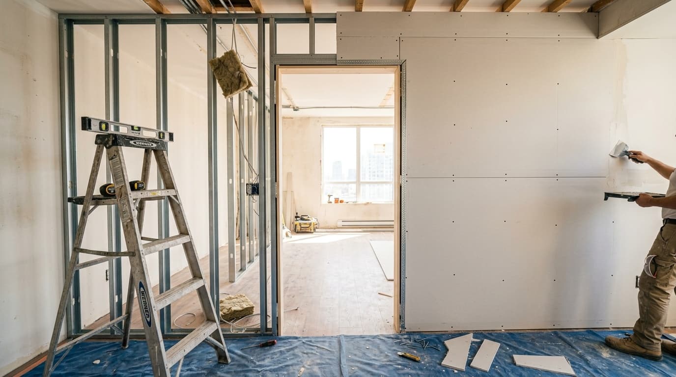
Aligning a drywall seam with the vertical jamb of a door or window opening guarantees a 45-degree diagonal crack within weeks of operation.
- Protocol: Panels surrounding openings must be notched out of a single continuous board in an L-shape (boot cut or flag cut), ensuring the board extends past the corner of the rough opening by at least 150–200 mm (6–8 in) (300 mm / 12 in recommended).
- Center the vertical joint above the door header within the middle third of the opening span over an intermediate stud.
3.3. Fastener Engineering and Depth Precision
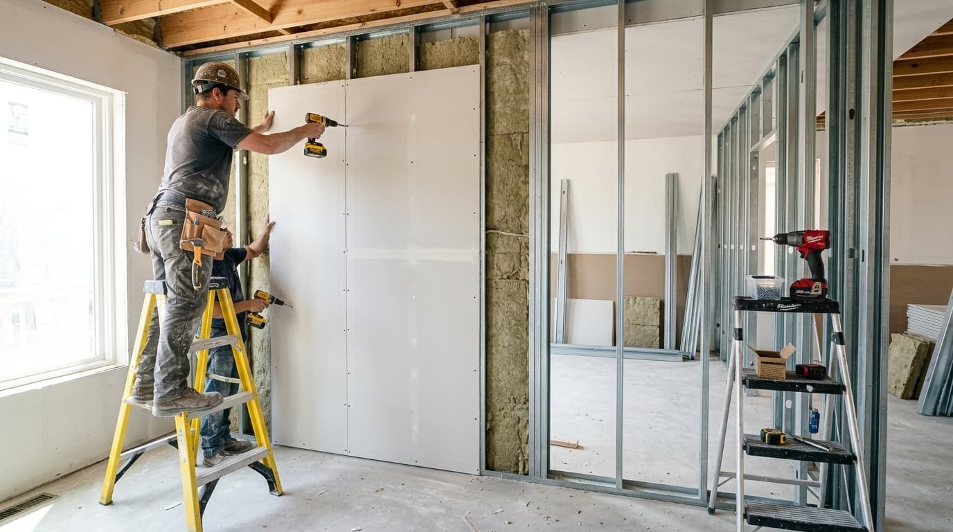
- Fastener Depth: Type TN (for 0.6 mm steel) or Type TB (self-drilling for up to 2.0 mm steel) drywall screws must be countersunk to a depth of exactly 0.8–1.0 mm (1/32 in) below the paper surface using a dedicated dimpler bit.
- Paper Rupture (Overdriving): The face paper liner provides the entire structural holding power. If the screw head cuts through the paper, the pull-through capacity drops from 320 N (72 lbs) to 0 N. The board floats unanchored, inducing vibration cracks.
- Screw Spacing:
- Ceilings: 150–170 mm (6 in) on center.
- Partitions & Linings: 250 mm (10 in) on center for single-layer (500 mm / 20 in for base layer in double-layer systems if face layer is immediately applied).
- Edge Margins:
- Minimum 10 mm (3/8 in) from factory paper-bound edges.
- Minimum 15 mm (5/8 in) from jobsite-cut butt edges.
3.4. Perimeter Expansion Clearances
- Floor Clearance: Gypsum boards must terminate 10 mm (3/8 in) above the structural slab or screed. This isolates the core from moisture wicking and prevents floor deflections from loading the wall panels.
- Ceiling Junction: Maintain a 2–3 mm (1/8 in) gap at wall-ceiling junctures, filled with acrylic/polyurethane acoustic sealant or jointed over Knauf Trennwandband separating tape.
4. Joint Chemistry, Taping Systems, and Edge Preps
4.1. Edge Preparation: Tapered (HRAK / AK) vs. Cut Butt Edges
- Factory Tapered Edge (HRAK / AK / PLUK): Engineered with a precise recess and unbroken paper liner to embed tape and filler flush with the face plane.
- Jobsite Cut Edges (Butt Joints): Raw cut edges feature square profiles and exposed, porous gypsum core.
- Beveling Protocol: Cut edges must be chamfered with a Knauf Kantenhobel beveling tool at 22.5° (forming a 45° combined V-groove) down to 2/3 of the board thickness (~8–9 mm for a 12.5 mm / 1/2 in board).
- Dust Removal & Priming: The cut core must be thoroughly dusted with a dry brush or damp sponge and primed with Knauf Tiefengrund penetrative primer. Applying joint compound over dry gypsum dust causes immediate flash-drying and bond delamination.
4.2. The Tape Debate: Why Self-Adhesive Mesh (Serpyanka) Fails
Self-adhesive fiberglass open-mesh tape (serpyanka) is responsible for a massive percentage of residential joint cracks. Under engineering analysis, mesh fails basic tensile criteria:
Tensile Joint Reinforcement Test (DIN EN 13963):
| Reinforcement Material | Tensile Strength | Failure Behavior |
|---|---|---|
| Self-Adhesive Fiberglass Mesh | ~ 110–130 N/mm² | Elongates up to 4%; core cracks INTERNALLY |
| Glass Non-Woven Fleece (Fleece tape) | ~ 140–180 N/mm² | Brittle shear rupture under moderate deflection |
| Knauf Kurt Micro-Perforated Tape | ~ 360–410 N/mm² | Rigid composite matrix; absorbs peak shear |
- Failure Mode of Fiberglass Mesh:
- Fiberglass mesh is applied dry to the board face before compound application. Filler cannot fully encapsulate the back threads, creating micro-voids.
- Fiberglass mesh exhibits high elasticity under initial load. It only develops full tensile resistance after the joint compound has already fractured internally by 0.5–1.0 mm.
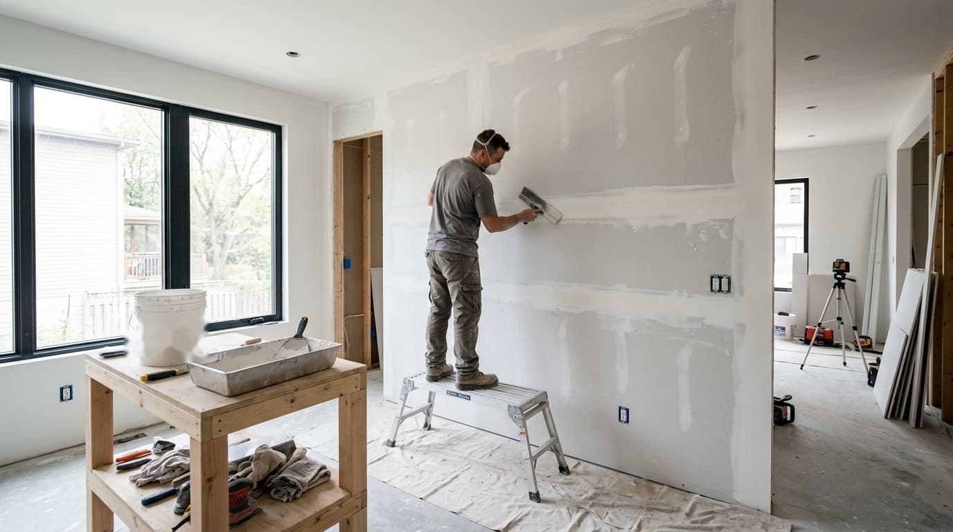
- Mechanics of Knauf Kurt Paper Tape: Manufactured from dimensionally stable, micro-perforated cellulose fibers with synthetic threading. Embedded directly into the bedding layer of compound, it forms a monolithic laminate with a tensile resistance exceeding 380 N/mm², preventing hairline fracture propagation.
4.3. Joint Compound Chemistry: Alpha-Hemihydrate vs. Ready-Mix Polymer Pastes
- Knauf Uniflott / Knauf Fugen (α-Hemihydrate High-Strength Gypsum):
- Hardens via chemical hydration (crystalline reaction), not moisture evaporation.
- Delivers near-zero volumetric shrinkage with compressive strength > 6.0 MPa (> 870 psi) and flexural strength > 2.5 MPa (> 360 psi).
- Requirement: Structural joint filling and bedding of Kurt tape must be executed exclusively with chemically setting α-hemihydrate compounds.
- Ready-Mix Polymer Bucket Pastes (Sheetrock / Rotband Pasta):
- Dry solely through water evaporation.
- Experience 15–20% volumetric shrinkage in deep joints and remain ductile and soft.
- Prohibition: Ready-mix air-drying bucket pastes must NEVER be used for the structural base coat (Stage 1) or inside V-grooves. They are strictly designated for continuous surface finishing (Q3/Q4 skimming).
4.4. Structural Movement & Expansion Joints
- Continuous ceilings and partitions must incorporate dedicated expansion joints every 10 to 15 meters (30 to 50 ft), and wherever the assembly crosses structural building expansion joints.
- Form control joints by interrupting both the metal grid and drywall panels by 10–20 mm (3/8 to 3/4 in), backed with Knauf expansion joint profiles or two separate uncoupled tracks filled with elastomeric sealants.
5. Interactive Partition & Ceiling Material Estimator
Use our Knauf Drywall Estimator below to calculate studs (CD/UD/CW/UW), gypsum sheets, damping tape, and fasteners for your exact room dimensions:
Knauf Drywall & Partition Calculator
Precise estimation for drywall partitions (W111, W112), wall linings (C623), and ceilings (D112)
Limit: 0.5 to 1,000 m
Limit: 1.0 to 20 m
400 mm for ceramic tiles
Determines wall thickness
Green for bathrooms & kitchens
3.0m for high ceilings
Limit: 0% to 30%
Limit: 0 to 50 openings
Limit: up to 999,999
Limit: up to 999,999
Detailed Material Specification (Knauf Standard)
All required components including profiles, fasteners, damping tape, joint tape and compound
| # | Material / Item | Quantity | Unit |
|---|---|---|---|
| 1 | Drywall Boards (Standard Drywall, 2.5x1.2m) Total: 25.08 m² (includes 8% waste allowance) | 9 | pcs |
| 2 | Track Profile (UW 50x40, 3m) Floor and ceiling perimeter track | 4 | pcs (3m) |
| 3 | Stud Profile (CW 50x50, 3m) Stud spacing: 600 mm | 13 | pcs (3m) |
| 4 | Acoustic Perimeter Sealing Foam Tape (Dichtungsband) Total: 17.4 linear meters (perimeter decoupling) | 1 | rolls (30m) |
| 5 | Hammer-Drive Anchors / Dowels 6x40mm Perimeter track and hanger base fixing | 50 | pcs |
| 6 | Drywall Screws Knauf TN 25mm (1") First layer drywall to metal stud fixing | 800 | pcs |
| 7 | Framing Metal-to-Metal Screws LN (Pancake Head) Stud-to-track and hanger assembly | 100 | pcs |
| 8 | Joint Reinforcing Tape (Knauf Kurt / Fiberglass) Total: 16.3m for taper and butt joints | 25 | meters |
| 9 | Joint Compound (Knauf Uniflott / Setting-Type) Ready-mix or powder setting compound | 9.9 | kg |
| 10 | Acoustic Mineral Wool Batts (50mm thick, 35-45 kg/m³) Total volume: 0.61 m³ (12.2 m²) | 3 | packs (~6 m²) |
Knauf Installation Rules & Common Pitfalls
- Perimeter Decoupling: Never mount guide profiles directly to concrete/screed without Dichtungsband tape. It prevents structural sound transmission and cracks.
- Staggered Seams: Butt seams between adjacent sheets must be staggered by at least 400 mm (16"). Cross-shaped 4-corner intersections are strictly forbidden.
- Fastener Depth: Screw heads must be countersunk by 1 mm into the board without tearing the paper liner.
Engineering Notes & Standards
Drywall assemblies calculated in strict accordance with Knauf technical bulletins and international framing standards (ASTM C754 / DIN 18181).
Acoustic Decoupling & Vibration
- Dichtungsband polymer tape under perimeter tracks reduces flanking noise transmission by 6–10 dB.
- Double-layer drywall (W112) with acoustic mineral wool achieves sound insulation index Rw up to 56–59 dB.
Framing & Fastener Rules
- For ceramic tile application, use 16" (400 mm) stud spacing and moisture-resistant boards.
- Do not use gypsum plaster on metal corners without rust-inhibiting coating.
6. Field Quality Control Checklist (8-Point Jobsite Inspection)
Certified Site Inspectors and Project Engineers must sign off on these 8 quality benchmarks prior to the commencement of surface painting or wallpapering:
- Substructure Steel Gauge: Verified minimum ≥ 0.60 mm (24 ga) certified steel across all tracks, studs, and furring channels. Zero stripped screws.
- Perimeter Decoupling: Continuous Knauf Dichtungsband foam tape confirmed beneath all perimeter floor, ceiling, and wall tracks.
- Sliding Ceiling Perimeter: CD 60/27 furring channels remain floating unattached inside UD 28/27 perimeter tracks with ≥ 10 mm (3/8 in) end clearance.
- Joint Stagger Distance: All transverse board joints staggered by ≥ 400 mm (16 in). Zero cruciform four-corner joints.
- Opening Geometry: All door and window rough opening corners wrapped with seamless L-shaped boot cut (flag cut) panels offset ≥ 150 mm (6 in) from corners.
- Fastener Precision: Drywall screws driven to a uniform depth of 0.8–1.0 mm (1/32 in) without paper tearing. Screw pitch ≤ 170 mm (6 in) on ceilings, ≤ 250 mm (10 in) on walls.
- Floor Clearance: Continuous 10 mm (3/8 in) gap maintained between the bottom edge of gypsum boards and the structural floor screed.
- Edge Prep & Taping: All cut edges beveled to 22.5°, dusted, primed with Tiefengrund, and reinforced with Knauf Kurt paper tape bedded in Knauf Uniflott setting compound.
Turn the idea into a working budget
Start with the main calculator, then use the two tools that most naturally follow this article.
This piece is grounded in the article topic, related calculations, and practical renovation decisions without extra theory.